Configuring the Location

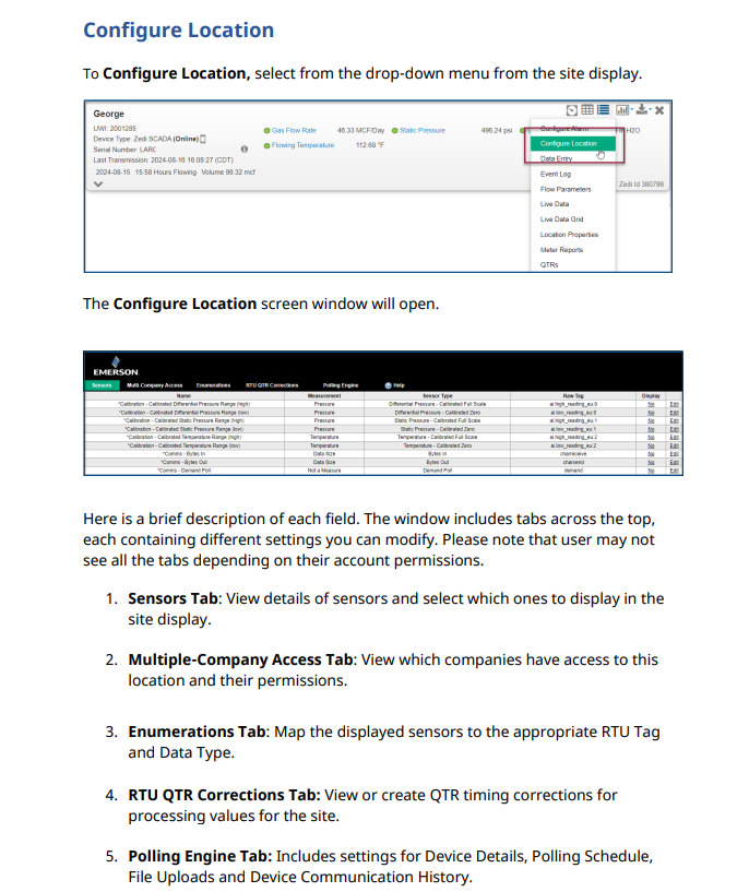
Click Configure Location in the Well Site Data Display drop down.


Image 339


The Configure Location Screen window opens.

Image 340


A brief description accompanies each field. There are tabs across the top of the window which contain separate groups of settings you can change. You may not see all of the tabs shown because of your configuration or account security permissions.
  1. In the Sensors Tab, select the sensors to display in the Wellsite Information Area of the Well Site Data Display window.
  2. In the MCAF Tab,you can view the multiple companies who have access to this location and what their permissions are.
  3. In the Enumerations Tab, map the Sensor being displayed with the appropriate RTU Tag and Data Type.
  4. In the RTU Meter Reports Tab,(if applicable), select the sensors that map to the appropriate fields for the report.
  5. The RTU QTR Corrections Tab is used to view/create QTR timing corrections applied to processing a yesterday value for Zedi SCADA sites.
  6. In the Pollsets Tab, combine different sensors (RTU register values) into groups called Pollsets, which can be triggered by a single command. Each Pollset requires unique sensors (RTU register values). Place basic sensors and yesterday value sensors in separate poll sets.
  7. In the Data Interval Tab, set the time interval, in minutes, that information is to be sent to Zedi Access. This feature is used for Well Testing, when fine resolution time data is required. The lowest interval you can set is one minute.
In the Reporting Interval Tab, configure your polling intervals. 

Is this article helpful for you?