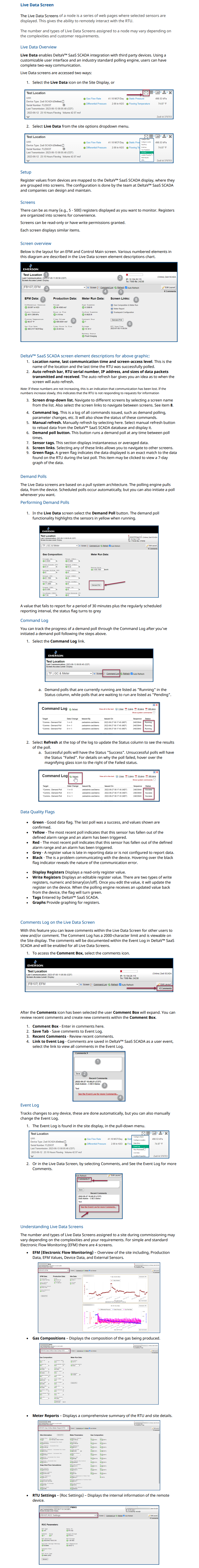
Live Data Screen

The Live Data Screens of a node is a series of web pages where selected sensors are displayed. This gives the ability to remotely interact with the RTU.​

The number and types of Live Data Screens assigned to a node may vary depending on the complexities and customer requirements.

Screen overview

Below is the layout for an EFM and Control Main screen. Various numbered elements in this diagram are described in the Live Data screen element descriptions chart.

Image 1721

Zedi SCADA screen element descriptions for above graphic:

1. Location name, last communication time and screen-access level. This is the name of the location and the last time the RTU was successfully polled.

2. Auto refresh bar, RTU serial number, IP address, and sizes of data packets transmitted and received. The auto refresh bar gives you an idea as to when the screen will auto refresh.

    Note: If these numbers are not increasing, this is an indication that communication has been lost. If the numbers increase slowly, this indicates that the RTU is not responding to requests for information


    3. Screen drop-down list. Navigate to different screens by selecting a screen name from the list. Also select the screen links to navigate between screens. See item 8.

    4. Command log. This is a log of all commands issued, such as demand polling, parameter changes, etc. It will also show the status of these commands.

    5. Manual refresh. Manually refresh by selecting here. Select manual refresh button to reload data from the Zedi SCADA database and display it.

    6. Demand poll button. This button runs a demand poll at any time between poll times.

    7. Sensor tags. This section displays instantaneous or averaged data.

    8. Screen links. Selecting any of these links allows you to navigate to other screens.

    9. Green flags. A green flag indicates the data displayed is an exact match to the data found on the RTU during the last poll. This item may be clicked to view a 7-day graph of the data.

      Demand Polls

      The Live Data screens are based on a pull system architecture. The polling engine pulls data, from the device. Scheduled polls occur automatically, but you can also initiate a poll whenever you want.

      Performing Demand Polls

      1. In the Live Data screen select the Demand Poll button. The demand poll functionality highlights the sensors in yellow when running.

        Image 1722

        A value that fails to report for a period of 30 minutes plus the regularly scheduled reporting interval, the status flag turns to grey.

        Command Log

        You can track the progress of a demand poll through the Command Log after you've initiated a demand poll following the steps above.

        1. Select the Command Log link.

        Image 1723

             a. Demand polls that are currently running are listed as "Running" in the Status column, while polls that are waiting to run are listed as "Pending".

        Image 1418

        2. Select Refresh at the top of the log to update the Status column to see the results of the poll.

             a. Successful polls will have the Status "Success". Unsuccessful polls will have the Status "Failed". For details on why the poll failed, hover over the magnifying glass icon to the right of the Failed status.

        Image 1419

          Live Data Overview

          Live Data enables Zedi Access integration with third party devices. Using a customizable user interface and an industry standard polling engine, users can have complete two-way communication.

          Live Data screens are accessed two ways:

          1. Select the Live Data icon on the Site Display, or

          Image 1724

          2. Select Live Data from the site options dropdown menu.

          Image 1725

          Setup

          Register values from devices are mapped to the Zedi Access display, where they are grouped into screens. The configuration is done by the team at Zedi and companies can design and maintain.

          Screens

          There can be as many (e.g., 5 - 500) registers displayed as you want to monitor. Registers are organized into screens for convenience.

          Screens can be read-only or have write permissions granted.

          Each screen displays similar items:

          Data Quality Flags

          • Green - Good data flag. The last poll was a success, and values shown are confirmed.
          • Yellow - The most recent poll indicates that this sensor has fallen out of the defined alarm range and an alarm has been triggered.
          • Red - The most recent poll indicates that this sensor has fallen out of the defined alarm range and an alarm has been triggered.
          • Grey - A register value is late in reporting data or is not configured to report data.
          • Black - The is a problem communicating with the device. Hovering over the black flag indicator reveals the nature of the communication error.
          • Display Registers Displays a read-only register value.
          • Write Registers Displays an editable register value. There are two types of write registers, numeric and binary(on/off). Once you edit the value, it will update the register on the device. When the polling engine receives an updated value back from the device, the flag will turn green.
          • Tags Entered by Zedi.
          • Graphs Provide graphing for registers.

          Comments Log on the Live Data Screen

          With this feature you can leave comments within the Live Data Screen for other users to view and/or comment. The Comment Log has a 2000-character limit and is viewable on the Site display. The comments will be documented within the Event Log in Zedi Access and will be enabled for all Live Data Screens.

          1. To access the Comment Box, select the comments icon.

          Image 1726

            After the Comments icon has been selected the user Comment Box will expand. You can review recent comments and create new comments within the Comment Box.

            1. Comment Box - Enter in comments here.
            2. Save Tab - Save comments to Event Log.
            3. Recent Comments - Review recent comments.
            4. Link to Event Log - Comments are saved in Zedi Access as a user event, select the link to view all comments in the Event Log.

            Image 1423

            Event Log

            Tracks changes to any device, these are done automatically, but you can also manually change the Event Log.

            1. The Event Log is found in the site display, in the pull-down menu.

            Image 1727

            2. Or in the Live Data Screen, by selecting Comments, and See the Event Log for more Comments.

            Image 1728

              Understanding Live Data Screens

              The number and types of Live Data Screens assigned to a site during commissioning may vary depending on the complexities and your requirements. For simple and standard Electronic Flow Monitoring (EFM) there are 4 screens.

              • EFM (Electronic Flow Monitoring) – Overview of the site including, Production Data, EFM Values, Device Data, and External Sensors.

              Image 1426

              • Gas Compositions – Displays the composition of the gas being produced.

              Image 1427

              • Meter Reports – Displays a comprehensive summary of the RTU and site details.

              Image 1428

              • RTU Settings – (Roc Settings) – Displays the internal information of the remote device.

              Image 1429

              This article was helpful for 1 person. Is this article helpful for you?