Configuring Alarms

ENABLE ALARMS 
A sensor must be enabled for alarms to be configured. To enable server alarms: 
1. In the site display, select the pull-down menu and select Configure Location. 

Image 1555

2. Find the sensor that to enable and select Edit. 

Image 1556

3. Select Enable Server Alarms.
4. Save. 

Image 1557

5. The sensor will now show in the Configure Tab in alarms and can be set.

Image 1558

SETTING ALARMS
  1. There are a few ways in which you can access the configure alarm screen to begin configuring them:

Image 372

a. The first option is to click the Options dropdown menu and select Configure Alarm. This will take you directly to the configure alarm screen for the site selected.

Image 374

Image 375

b. The second option is to select from the colored Alarm icons on the top right of the screen. This will take you to the configure alarms screen where you will select Configure and select the Location.

Image 376


Image 377

c. Finally, you can select Alarms in the Admin pull down menu in the top left of the home page. This will take you to the configure alarms screen where you will select Configure and select the Location.


2. Once you are in the configure screen, choose the sensor you would like to set the alarm for by selecting the name in blue. (ie. Gas Flow Rate)

Image 378

    At a quick glance you are able to see what the, UOM is, and what the High High and Low Low is set at.
    The person icon indicates if there is a contact should the alarm be triggered. (Red indicates no contact has been set up)

    Image 379

    3. Enter the value you would like the alarm to be tripped or set at for High High/Low Low and High/Low under the Set Level field. Enter your normal or reset value for each trip point.
    a. Alarm Configuration settings available for a server alarm are:
    b. High High Set Level the level at which the high high alarm event triggers.
    c. High High Reset Level the level at which the high high alarm event is cleared. High High Reset Level Value = Set Level          Value – Hysteresis
    d. High Set Level the level at which the high alarm event triggers.
    e. High Level Reset the level at which the high alarm event clears. High Reset Level Value = Set Level Value – Hysteresis
    f. Low Set Level the level at which the low alarm event triggers.
    g. Low Reset Level the level at which the low alarm event clears. Low Reset Level Value = Set Level Value + Hysteresis
    h. Low Low Set Level the level at which the low low alarm event triggers.
    i. Low Low Reset Level the level at which the low low alarm event is cleared. Low Low Reset Level Value = Set Level Value      + Hysteresis
    j. Hysteresis Set Time- After the ‘x’ seconds, the RTU will demand poll and confirm whether that sensor is still in alarm          state or if the alarm can be cleared. It will ultimately check the alarm status twice to confirm whether an alarm should be     initiated or cleared
    4. You can change the dates to View Data from a specific range.
    5. You can hover over the graph to see the exact time, date and gas flow rate. 
    6. Select Test to ensure the parameters are enabled.
    7. Click Save.

      Image 380


      View data graphs the dates selected for a quick view of alarms on this site.
      MESSAGE
      Messages can be customized to suit the device, person, or message center receiving the email or text message. The well site location, the device Instrument ID, sensor type, alarm value, and the date and time of the alarm event as registered by the server can be sent in a text message. A very simple message can be used to convey only the relevant data. A short message like the example below may be used when the device has limited message length capability, or when the recipient is familiar with the alarms that have been set up.
      Example:
      An alarm event occurred at #TIM on the PAC, PAC2, or PAC4 #SDS, located at Battery #LOC in Field #FLD for XYZ Exploration Ltd. The sensor measuring #SEN with a value of #AMT is outside the range set at #MIN - #MAX. Please call John Smith at 780-555-5555.

      Message formats are:

      #FLD-Field Name
      #MAX-Alarm Maximum
      #AMT-Reading Amount
      #VALUE [equivalent to #AMT]
      #SEN-Sensor Name
      #TIM-Time and Date
      #MIN-Alarm Minimum
      #ERR-High or Low
      #LOC-Well Location
      #WELL-equivalent to #LOC
      #HIERARCHY

      Image 381

      1. Select Message for this sensor only or Message for entire location.
      2. Select Test to see if the message is sent out to the user and in the format that is required by the end user.
      3. Select Save.
      CONTACT
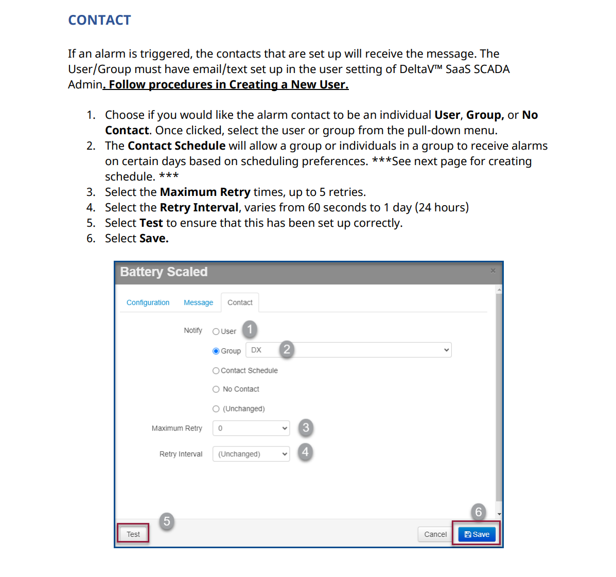
      If an alarm is triggered, the contacts that are set up will receive the message. The User/Group must have email/text set up in the user setting of Zedi Admin. Follow procedures in Creating a New User.

      Image 382


      1. Choose if you would like the alarm contact to be an individual User, Group, or No Contact. Once clicked, select the user or group from the pull-down menu.
      2. The Contact Schedule will allow a group or individuals in a group to receive alarms on certain days based on scheduling preferences. ***See next page for creating schedule. ***
      3. Select the Maximum Retry times, up to 5 retries.
      4. Select the Retry Interval, varies from 60 seconds to 1 day (24 hours)
      5. Select Test to ensure that this has been set up correctly.
      6. Select Save.

      This article was helpful for 1 person. Is this article helpful for you?